Tekla Structural Designer (TSD) is a simple, integrated design & analysis software that enables engineers to deliver safe, effective and rationalized design more quickly, regardless of structural material. Reinforcement drawings for the entire building or tonnes of steel for estimating, all available in the touch of a button.
Eccentric footings are used where there are restrictions on the usable Ground Area outside the Building Built-up area (Due to other Building, Plot Boundary etc.).
In Tekla Structural Designer we can Design Isolated Footings, and by changing the eccentricity of the footings provided we can easily design eccentric footings.
The Points mentioned below will provide a stepwise guide to model and design eccentric footings in Tekla Structural Designer.
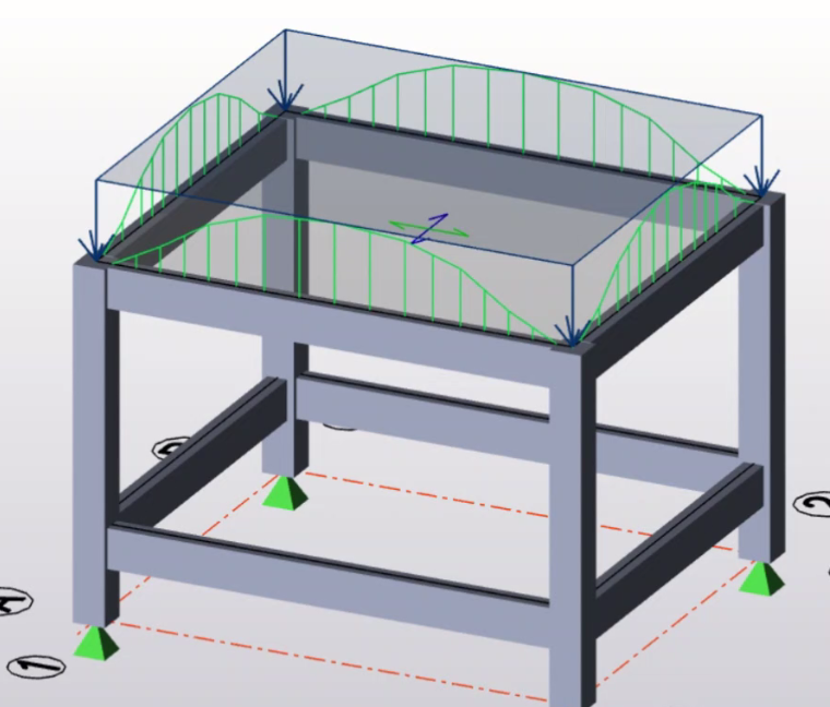
Step1: Before Starting we need to ensure that we have a building model in which all the loads are applied properly and it is analysed and designed.
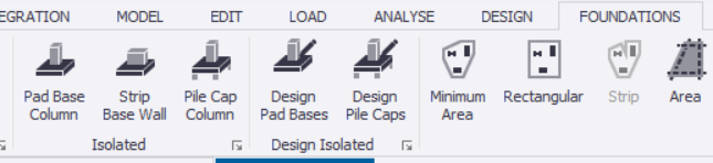
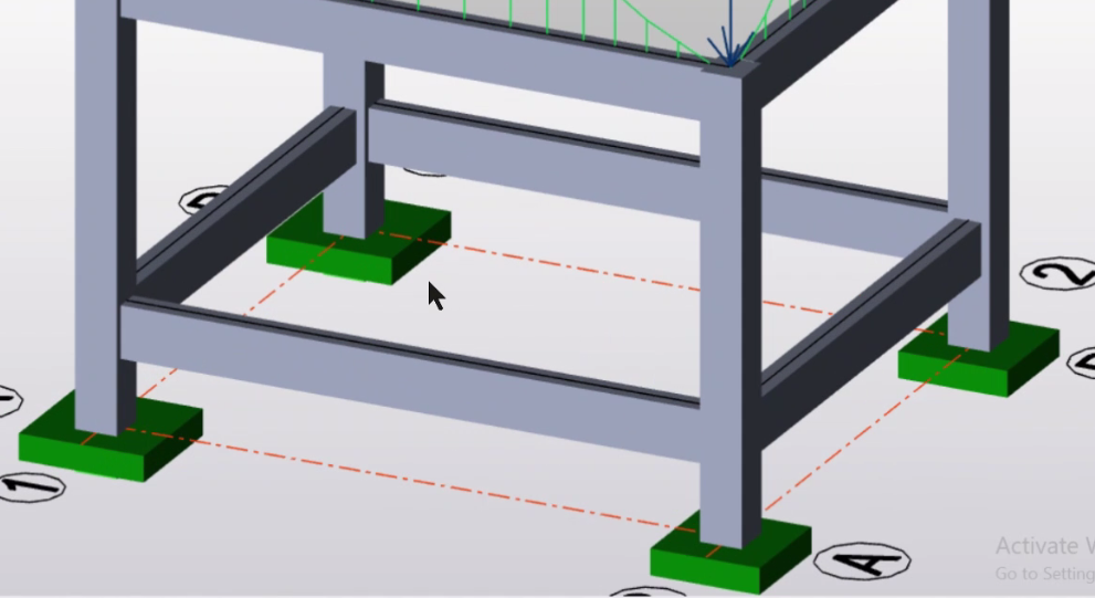
Step2: Select Foundations-Pad Base Column, assign the Pad Base columns below the columns.
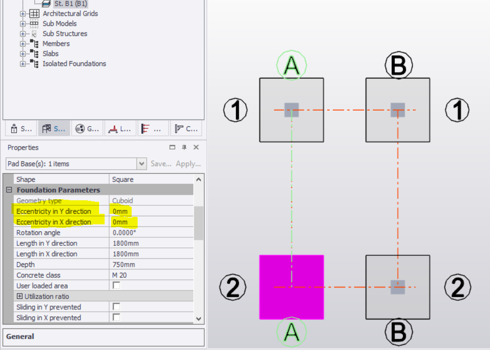
Step3: Go to the Foundation Level, Select the applied foundation or footing which you want to make as eccentric. In the properties menu change the eccentricity in x and y directions as per your requirements.
Step4: Go to Foundation- Design Pad bases. The eccentric footing will then be designed.
Step5: Go to the Foundation Level, Click on “Foundation Layout” for viewing the design results of the footing. Click on ok after a small window appears.
Like this we can view the design results and drawing of the eccentric footing.
For Knowing in Details you can watch this Video: https://youtu.be/XkC4bytWpDg
About us: Civil Center is a Civil Engineering Consultancy company which provides services ranging from Building Consultancy Services like Architectural Plan, Structural Drawing, Estimation, 3D Views of Interior and Exterior of a Building, Construction Planning and Management, and also other services like Survey Investigation Works.

We also provide industrial Training to Civil Engineering Students as well as professionals which include courses on Building Design, Detailing Estimation, 3D Modelling and Survey by using Software like STAAD. Pro, Tekla Structural Designer, Revit Structures, Tekla Structures, MS Excel, E-Survey. In training our goal is to make our trainees ready for the industry by getting them trained in Live Projects. We also provide placement assistance to our trainees.
To join our live classes on Tekla Structural Designer and other courses related to Civil Engineering, click here : https://forms.gle/Yy9j8BH8zZzmFfZMA
For any query
Call on: 8433248864
WhatsApp: +91 6372905201
Email: team@civilcenter.in
If you have any requirement of Building Consultancy Services like Architectural Plan, Structural Drawings etc., register using the link given below
https://forms.gle/M4MTqgcLP6ZEp4rs7
Whatsapp: +91 6372905201
Email: enquiry@civilcenter.in
Visit our Website: http://www.civilcenter.in/
Visit our Website: http://www.civilcenter.in/
You Can Find Us On Other Social Media
Follow us on Telegram :https://t.me/civilcenter17
Visit our Facebook Page: https://www.facebook.com/civilcenter/
Visit our LinkedIn Page: https://www.linkedin.com/company/civil-center
Follow our Twitter Handle: https://twitter.com/_CivilCenter
Follow us on Instagram: https://www.instagram.com/civilcenter17/
Comments
Post a Comment