
How to apply Wind Load In Irregular Building!! Tekla Structural Designer.

 In structural design, wind load is a type of lateral load which plays a very important role, especially if the building height is more than 10 m and the building is in a cyclone-prone zone. When wind acts on a building or any type of structure, the resulting force acting on the building elevation is called "wind load".

The magnitude of the wind load depends upon the angle at which the wind makes contact with the building and also the structure size (Viz. height, width)


In this blog, we are going to discuss how to apply wind loads on irregular buildings.

So let's start the step by step procedure 


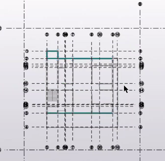
Step 1: Let us consider an irregular building model in Tekla structural design and go to base level, draw some construction lines by taking offsets from existing construction lines. 

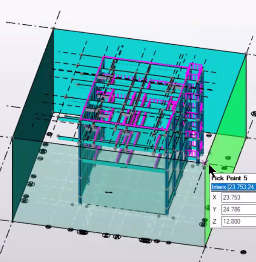
Step 2: Also go to the topmost level and in the properties menu tick the option of Show Grids in 3D.

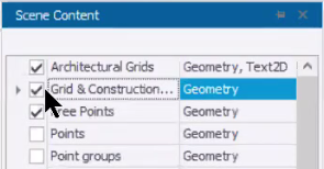
Step 3: Turn on the gridline visibility in the 3D View from the scene content menu


Step 4: Go to model option and select wall panels and create panels around the irregular building model, cover it from all the sides so that a surface is present for the wind loads to act.


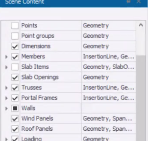
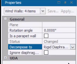
Step 5: Go to scene content and turn on wind panels and select all the panels and select all the panels and tick on the rigid diaphragm option from the properties menu.


Step 6: Then go loading and select wind wizard and give basic wind speed value and all other requisites, as per your building Design Code selected. 

Step 7: Under the Load option, create the required load combinations, and then in the design option, click on “Design All Static”, to check the design results


About us: Civil Center is a Civil Engineering Consultancy company which provides services ranging from Building Consultancy Services like Architectural Plan, Structural Drawing, Estimation, 3D Views of Interior and Exterior of a Building, Construction Planning and Management, and also other services like Survey Investigation Works.


We also provide industrial Training to Civil Engineering Students as well as professionals which include courses on Building Design, Detailing Estimation, 3D Modelling and Survey  by using Software like STAAD. Pro, Tekla Structural Designer, Revit Structures, Tekla Structures, MS Excel, E-Survey. In training our goal is to make our trainees ready for the industry by getting them trained in Live Projects. We also provide placement assistance to our trainees.

To join our live classes on Tekla Structural Designer and other courses related to Civil Engineering, click here : https://forms.gle/Yy9j8BH8zZzmFfZMA

For any query 

Call on: 8433248864

WhatsApp: +91 6372905201

Email: team@civilcenter.in


If you have any requirement of Building Consultancy Services like Architectural Plan, Structural Drawings etc., register using the link given below

https://forms.gle/M4MTqgcLP6ZEp4rs7

Whatsapp: +91 6372905201

Email: enquiry@civilcenter.in

Visit our Website: http://www.civilcenter.in/


Visit our Website: http://www.civilcenter.in/


You Can Find Us On Other Social Media

Visit our Facebook Page: https://www.facebook.com/civilcenter/

Visit our LinkedIn Page: https://www.linkedin.com/company/civil-center

Follow our Twitter Handle: https://twitter.com/_CivilCenter

Follow us on Instagram: https://www.instagram.com/civilcenter17/

Comments

Popular posts from this blog

How to study the Reinforcement Drawings of beams which have been generated in TSD.

Tekla Structural Designer is advanced software used for Structural Analysis and Design of a Building. In Tekla, we can do the detailing of steel structures as well as RCC structures. We can create RCC buildings and we can insert the rebars in Tekla structures Designer software.  We can also do the form works and structural drawing without the help of any other software. Let’s go step by step to learn how to study the Reinforcement Drawings of beams that have been generated in TSD. Step 1 As we can see, this building has been fully designed and analysed. Now, just right click on the beam then click on the report for the member and it will generate the report for the member and we will see this and after that, we can also check the file for the particular beam.     Fig.1 Step 2 Now we have 3 numbers of sections, for each beam, it has been made and the respective cross-section is also given. Step 3 Now if we just go through the drawing, we can see that we have 2 bars of 16mm at the top an

How to Provide Reinforcement in multiple columns in Tekla Structures

  Tekla Structures is a Building Information Modeling (BIM) software able to model structures that incorporate different kinds of building materials, including steel, concrete, timber and glass. However it is widely used for the detailing of structural drawing.  In this blog, we are going to discuss how  to provide reinforcement in multiple columns in Tekla Structures.  So let's start the step by step procedure Step 1 : At first we must make sure that our model is correct and after that we will look for the column reinforcement application.   Step 2 : Search result will give us lots of options which includes application of column (for both the RCC and steel).  Step 3 : Now from there we have to select an app for RCC. column.  Step 4 : We will go for Application no. 57 which is "Column automated reinforcement layout". Step 5 : Select and define the application according to our requirement. Now select all the columns by dragging the mouse from right to left. It will select

STAAD Pro Vs Tekla Structural Designer .Which One Is Better ?

  Tekla Structural Designer (TSD) is a simple, integrated design & analysis software that enables engineers to deliver safe, effective and rationalized design more quickly, regardless of structural material. Reinforcement drawings for the entire building or tonnes of steel for estimating and many more.    So in the above image you can see the first image is created in Tekla Structural Designer (TSD) and in the second image the model has been created in Staad Pro  . we can start the comparison with the grid lines. So for creating grid lines in staad we need to enter the coordinates from the beam column plan as shown in fig.1 and we need to insert it while viewing the beam column plan. Fig 1 We can create grid lines in Tekla Structural Designer directly and in addition        you can also import the beam column plan as shadow as shown in fig 2 .  Fig. 2 • Next step is adding members in staad pro so in addition we need to see the beam column plan again and again so that we can place