A survey is a method of gathering information from a sample of people, traditionally with the intention of generalising the results to a larger population.Surveys provide a critical source of data and insights for nearly everyone engaged in the information economy, from businesses and the media to government and academics.
Instruments used in survey
Theodolite
Total station
Transit level
Auto level
Dumpy level
The instrument that is mostly used in survey is Total station.
About Total station
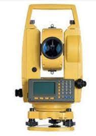
A total station is an optical surveying instrument that uses electronics to calculate angles and distances. It combines the functions of a theodolite with that of a transit level and electronic distance meter (EDM).
Function of total station :
Angle measurement
Most total station instruments measure angles by means of electro-optical scanning of extremely precise digital bar-codes etched on rotating glass cylinders or discs within the instrument. The best quality total stations are capable of measuring angles to 0.5 arc second. Inexpensive "construction grade" total stations can generally measure angles to 5 or 10 arc-seconds.
Distance measurement
Measurement of distance is accomplished with a modulated infrared carrier signal, generated by a small solid-state emitter within the instrument's optical path, and reflected by a prism reflector or the object under survey. The modulation pattern in the returning signal is read and interpreted by the computer in the total station. The distance is determined by emitting and receiving multiple frequencies, and determining the integer number of wavelengths to the target for each frequency. Most total stations use purpose-built glass prism reflectors for the EDM signal.
Coordinate measurement
The coordinates of an unknown point relative to a known coordinate can be determined using the total station as long as a direct line of sight can be established between the two points. Angles and distances are measured from the total station to points under survey, and the coordinates (X, Y, and Z; or easting, northing, and elevation) of surveyed points relative to the total station position are calculated using trigonometry and triangulation .
Data processing
Some models include internal electronic data storage to record distance, horizontal angle, and vertical angle measured, while other models are equipped to write these measurements to an external data collector, such as a hand-held computer.
When data is downloaded from a total station onto a computer, application software can be used to compute results and generate a map of the surveyed area. The newest generation of total stations can also show the map on the touch-screen of the instrument immediately after measuring the points.
For more details, watch this: https://youtu.be/9q22KwcJXXg
About us: Civil Center is a Civil Engineering Consultancy company which provides services ranging from Building Consultancy Services like Architectural Plan, Structural Drawing, Estimation, 3D Views of Interior and Exterior of a Building, Construction Planning and Management, and also other services like Survey Investigation Works.

We also provide industrial Training to Civil Engineering Students as well as professionals which include courses on Building Design, Detailing Estimation, 3D Modelling and Survey by using Software like STAAD. Pro, Tekla Structural Designer, Revit Structures, Tekla Structures, MS Excel, E-Survey. In training our goal is to make our trainees ready for the industry by getting them trained in Live Projects. We also provide placement assistance to our trainees.
To join our live classes on Tekla Structural Designer and other courses related to Civil Engineering, click here : https://forms.gle/Yy9j8BH8zZzmFfZMA
For any query
Call on: 8433248864
WhatsApp: +91 6372905201
Email: team@civilcenter.in
If you have any requirement of Building Consultancy Services like Architectural Plan, Structural Drawings etc., register using the link given below
https://forms.gle/M4MTqgcLP6ZEp4rs7
Whatsapp: +91 6372905201
Email: enquiry@civilcenter.in
Visit our Website: http://www.civilcenter.in/
Visit our Website: http://www.civilcenter.in/
You Can Find Us On Other Social Media
Follow us on Telegram :https://t.me/civilcenter17
Visit our Facebook Page: https://www.facebook.com/civilcenter/
Visit our LinkedIn Page: https://www.linkedin.com/company/civil-center
Follow our Twitter Handle: https://twitter.com/_CivilCenter
Follow us on Instagram: https://www.instagram.com/civilcenter17
Comments
Post a Comment