In modern framed structure buildings (RCC Buildings), masonry plays the role of a partition wall which is provided for the purpose of privacy, aesthetical view points and protecting the inhabitants of the building from the external environment.
Most common materials used in masonry are AAC Blocks and Bricks. So how can we define bricks in a simple manner?
“Brick is a type of rectangular block used for masonry construction.”
Although sometimes bricks may have other unconventional shapes for suiting architectural requirements. Among the common types of bricks used are Burnt Clay Bricks, Fly Ash Bricks and Hollow Bricks. In many places especially in some states of India the manufacture of red bricks has been banned, since it utilises the top alluvial layer of the soil, which is very useful in agriculture (the income generating source for the majority of the population of the country.)
So, let us briefly go through the manufacturing process of Fly Ash bricks.
Manufacturing process of Fly Ash Brick
Mixing: The process involves mixing of fly ash, sand/stone dust, lime and gypsum in the proper proportions.
Firstly mixing lime and gypsum are grinded and mixed with some water, next fly ash and sand/stone dust are added to the mix.
Cement can also be used in place of lime and gypsum, in that case the dry mix of fly ash and sand/stone dust is prepared first, then cement is mixed and after that a proper amount of water is added and mixed.
Moulding: The mixture is then transferred to the moulding machine, where it is hydraulically pressed through vibrations using vibratory press.
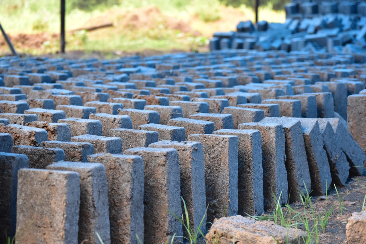
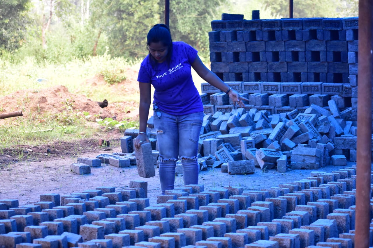
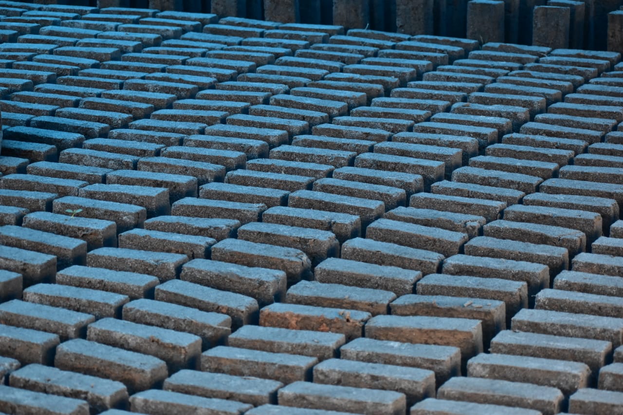
Drying: The prepared bricks are taken out of moulds and dried for about 2 days.
Curing: Water Curing of the dried bricks is done for 14 days, so that the brick gains the desired strength.
About us: Civil Center is a Civil Engineering Consultancy company which provides services ranging from Building Consultancy Services like Architectural Plan, Structural Drawing, Estimation, 3D Views of Interior and Exterior of a Building, Construction Planning and Management, and also other services like Survey Investigation Works.

We also provide industrial Training to Civil Engineering Students as well as professionals which include courses on Building Design, Detailing Estimation, 3D Modelling and Survey by using Software like STAAD. Pro, Tekla Structural Designer, Revit Structures, Tekla Structures, MS Excel, E-Survey. In training our goal is to make our trainees ready for the industry by getting them trained in Live Projects. We also provide placement assistance to our trainees.
To join our live classes on Tekla Structural Designer and other courses related to Civil Engineering, click here : https://forms.gle/Yy9j8BH8zZzmFfZMA
For any query
Call on: 8433248864
WhatsApp: +91 6372905201
Email: team@civilcenter.in
If you have any requirement of Building Consultancy Services like Architectural Plan, Structural Drawings etc., register using the link given below
https://forms.gle/M4MTqgcLP6ZEp4rs7
Whatsapp: +91 6372905201
Email: enquiry@civilcenter.in
Visit our Website: http://www.civilcenter.in/
Visit our Website: http://www.civilcenter.in/
You Can Find Us On Other Social Media
Visit our Facebook Page: https://www.facebook.com/civilcenter/
Visit our LinkedIn Page: https://www.linkedin.com/company/civil-center
Follow our Twitter Handle: https://twitter.com/_CivilCenter
Follow us on Instagram: https://www.instagram.com/civilcenter17/
Comments
Post a Comment