
How to copy & edit loads of the members in the Tekla structural designer?

 Tekla structural designer (TSD) is a simple, integrated design & analysis software that gives engineers the power to analyze and design buildings efficiently and profitably. As we know that a structure will be applied with many loads like dead load, imposed load, wind loads etc.., Let us know how to copy and apply the load of one member to another member.

Step 1

Open up the TSD software and in 3D view, you can see the loading pattern of the designed structure (in the form of dead load)
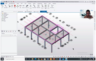
 

Fig.1


Step 2

To know the loading magnitudes of a particular member- select it and under the properties section select load(s): 1 items option.

You can change the magnitude of the load on selected members over there.
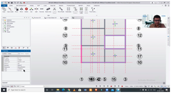
 

          Fig.2

Step 3 

To copy a load of that member into another member, go to the edit option and then click on copy loads in the toolbar.

  • Then simply go on to the structure and select the member of which load to be copied and click on another member of the structure to apply the copied load.

  • And then you can cross-check whether the load is applied or not by following step 2.
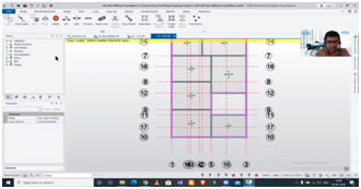
 

Fig.3

To copy and edit the different loads (imposed, wind, etc..,) on members follow the same process.


For more details, watch this: 

Tekla Structural Designer: Copying and Editing Loads


What is TEKLA? | TEKLA Structural Designer | CIVIL CENTER


About us: Civil Center is a Civil Engineering Consultancy company which provides services ranging from Building Consultancy Services like Architectural Plan, Structural Drawing, Estimation, 3D Views of Interior and Exterior of a Building, Construction Planning and Management, and also other services like Survey Investigation Works.


We also provide Industrial Training to Civil Engineering Students as well as professionals which include courses on Building Design, Detailing Estimation, 3D Modelling and Survey by using Software like STAAD. Pro, Tekla Structural Designer, Revit Structures, Tekla Structures, MS Excel, E-Survey. In training, our goal is to make our trainees ready for the industry by getting them trained in Live Projects. We also provide placement assistance to our trainees.

To join our live classes on Tekla Structural Designer and other courses related to Civil Engineering, click here : https://forms.gle/Yy9j8BH8zZzmFfZMA

For any query 

Call on: 8433248864

WhatsApp: +91 6372905201

Email: team@civilcenter.in


If you have any requirement of Building Consultancy Services like Architectural Plan, Structural Drawings etc., register using the link given below

https://forms.gle/M4MTqgcLP6ZEp4rs7

Whatsapp: +91 6372905201

Email: enquiry@civilcenter.in

Visit our Website: http://www.civilcenter.in/


Visit our Website: http://www.civilcenter.in/


You Can Find Us On Other Social Media

Follow us on Telegram :https://t.me/civilcenter17

Visit our Facebook Page: https://www.facebook.com/civilcenter/

Visit our LinkedIn Page: https://www.linkedin.com/company/civil-center

Follow our Twitter Handle: https://twitter.com/_CivilCenter

Follow us on Instagram: https://www.instagram.com/civilcenter17/

Comments

Popular posts from this blog

Tekla structural Designer VS ETABS.

Tekla Structural Designer is advanced software used for Structural Analysis and Design of a Building. In Tekla, we can do the detailing of steel structures as well as RCC structures. We can create RCC buildings and we can insert the rebars in Tekla structures Designer software.  We can also do the form works and structural drawing without the help of any other software. Let’s see the difference between TSD and ETABS. Step 1 As per the modelling aspects in ETABS we can import the grid lines we cannot import the shadow of an architectural drawing and in Tekla, we can import grid lines as well as the shadow of an architectural drawing assigning beams and columns is very easy and the modelling becomes quick.  In ETABS we cannot see the extruded view easily but in TSD we can see the extruded view easily. Basically, visualization is easy in TSD as compared to ETABS.   Step 2 In TSD load application is very easy as the dead load and live load both are almost same but in the wind...

STAAD Pro Vs Tekla Structural Designer .Which One Is Better ?

  Tekla Structural Designer (TSD) is a simple, integrated design & analysis software that enables engineers to deliver safe, effective and rationalized design more quickly, regardless of structural material. Reinforcement drawings for the entire building or tonnes of steel for estimating and many more.    So in the above image you can see the first image is created in Tekla Structural Designer (TSD) and in the second image the model has been created in Staad Pro  . we can start the comparison with the grid lines. So for creating grid lines in staad we need to enter the coordinates from the beam column plan as shown in fig.1 and we need to insert it while viewing the beam column plan. Fig 1 We can create grid lines in Tekla Structural Designer directly and in addition        you can also import the beam column plan as shadow as shown in fig 2 .  Fig. 2 • Next step is adding members in staad pro so in addition we need to see the beam colu...

How to study the Reinforcement Drawings of beams which have been generated in TSD.

Tekla Structural Designer is advanced software used for Structural Analysis and Design of a Building. In Tekla, we can do the detailing of steel structures as well as RCC structures. We can create RCC buildings and we can insert the rebars in Tekla structures Designer software.  We can also do the form works and structural drawing without the help of any other software. Let’s go step by step to learn how to study the Reinforcement Drawings of beams that have been generated in TSD. Step 1 As we can see, this building has been fully designed and analysed. Now, just right click on the beam then click on the report for the member and it will generate the report for the member and we will see this and after that, we can also check the file for the particular beam.     Fig.1 Step 2 Now we have 3 numbers of sections, for each beam, it has been made and the respective cross-section is also given. Step 3 Now if we just go through the drawing, we can see that we have 2 ba...