Watch this:
How Response Spectrum Analysis is done in Tekla ?
What is TEKLA? | TEKLA Structural Designer | CIVIL CENTER
Tekla Structural Designer is an advanced software used for Structural Analysis and Design of a Building.In Tekla we can do detailing of steel structures as well as RCC structures we can create RCC buildings and we can insert the rebars in Tekla structures Designer software. We can also do the form works and structural drawing without the help of any other softwares .
By following the steps you can know about how to response spectrum analysis in TSD:
To understand the concept of Response Spectrum Analysis in TSD , First we need to create a small and simple building model. For that first we need to open a new TSD model then go to model and click on Construction Level to create Construction level for a small building model.
- Now we need to insert a level below its -1.2m and insert level above giving spacing of 3.2 and change type to S.S.L(Structural Slab Level) and give its slab thickness of 100mm. Now after we have done this now if we want to see the levels what we have created for that go to structural Window you can see your level option andhere all the levels are created.
- Now we have to create the Grid line for that. First we need to go to the plinth level that is the structural base then go to the grid line option and we will use a rectangular wizard to create the grid line. Letscreat grid line in x-direction, select bays take count 1 and take length 6m now in Y-direction take count 1 and length 4m and click Next and again Next and then Finish.
- Once the grid line is created now it's time to create the column, so go to the concrete section and click on the column and in this column properties there are various options but we will just choose the default option, now to create a column we need to simply drag on the grid lines and columns will be created.
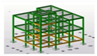
- Now in the Plinth level we will also create the beams and in the st.(1) level create beams and as well as our slab also.After that we can see that a simple structure has been created.
- Next step is to apply some loads, so we will apply basic Live load for that go to St. 1(1) Level and we will use basic imposed load and go to Load and take area load or even we can take Level load let’s take level load of 2 KN/m2.
- Now let’s create Seismic load for that go to Load click on Seismic load and go to seismic Wizard and then code spectra and change Ignore seismic in floor (and below) to Plinth level and take Importance Factor as 1 for a normal building and click on Next and select Use modal response spectrum Analysis and click on next, now change structure type to RC MRF Building without any masonry infills on both Fundamental Period Dir 1 and 2 and click on Next, now change type of Seismic Force Resisting System Dir 1 and 2 to i) Moment Frame System and then Next now we will just sift all loadcase consideration of all live and dead loads to right Next and then Finish.
- After this a Combination Generator will appear and go to the scenario and click on operating and next and in combination as in the Indian standard we will go with the Limit State combination due to the seismic load and then Next and Finish .
- After that we will just go to load and create the Load Combination and click on generate, keep the scenario as operating and Next and in combination limit state will select only and Next again Next, Finish And click on OK.
- And now go to Design, in Analysis & Design click on Design all (Static).
- After design we need to select all of the columns and go to its properties. Here we can see the seismic zone, we just click on In a seismic force resisting system and keep SFRS direction as D1 but we need to change SFRS type to Ordinary Moment Frame.
- Now After that we select all the beams and go to the seismic zone and change SFRS direction as D1 & D2 and change SFRS type as Ordinary moment frame.
- Now after having done that we will just go to design and Design All (RSA).
- As we see, the building has been designed as per RSA.
- Now let’s check the design for that select any member then right click on it then go to interactive design and RSA and now we can see the RSA design.
So I hope you can now understand how response spectrum analysis is done in Tekla Structural Designer(TSD).
For more details, watch this:
How Response Spectrum Analysis is done in Tekla ?
What is TEKLA? | TEKLA Structural Designer | CIVIL CENTER
About us: Civil Center is a Civil Engineering Consultancy company which provides services ranging from Building Consultancy Services like Architectural Plan, Structural Drawing, Estimation, 3D Views of Interior and Exterior of a Building, Construction Planning and Management, and also other services like Survey Investigation Works.

We also provide Industrial Training to Civil Engineering Students as well as professionals which include courses on Building Design, Detailing Estimation, 3D Modelling and Survey by using Software like STAAD. Pro, Tekla Structural Designer, Revit Structures, Tekla Structures, MS Excel, E-Survey. In training, our goal is to make our trainees ready for the industry by getting them trained in Live Projects. We also provide placement assistance to our trainees.
To join our live classes on Tekla Structural Designer and other courses related to Civil Engineering, click here : https://forms.gle/Yy9j8BH8zZzmFfZMA
For any query
Call on: 8433248864
WhatsApp: +91 6372905201
Email: team@civilcenter.in
If you have any requirement of Building Consultancy Services like Architectural Plan, Structural Drawings etc., register using the link given below
https://forms.gle/M4MTqgcLP6ZEp4rs7
Whatsapp: +91 6372905201
Email: enquiry@civilcenter.in
Visit our Website: http://www.civilcenter.in/
Visit our Website: http://www.civilcenter.in/
You Can Find Us On Other Social Media
Follow us on Telegram :https://t.me/civilcenter17
Visit our Facebook Page: https://www.facebook.com/civilcenter/
Visit our LinkedIn Page: https://www.linkedin.com/company/civil-center
Follow our Twitter Handle: https://twitter.com/_CivilCenter
Follow us on Instagram: https://www.instagram.com/civilcenter17/
Comments
Post a Comment