
RCC Slab: How Placement of Electrical Conduits & Reinforcement arrangement

 Let us take a virtual tour of a  building construction site for checking Electrical conduit in RCC slab and reinforcement arrangement  which is going to be cast.


Conduit Electrical system is the most common type of Electrical wiring. Mostly PVC conduits are used in domestic wiring.


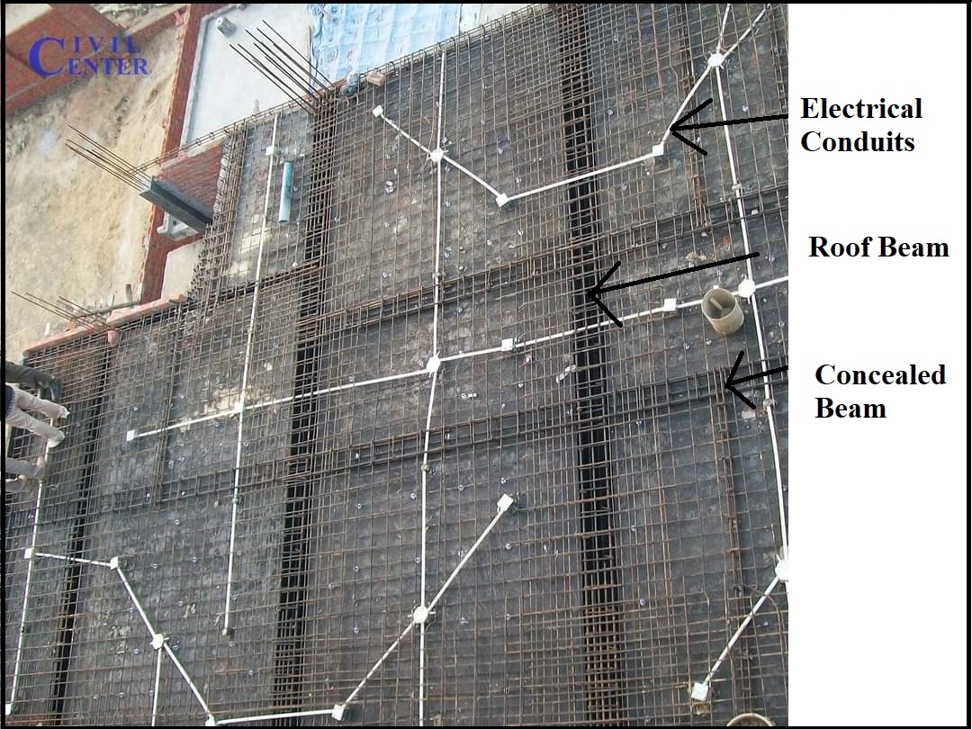
What is visible at the site

1-Electrical conduits as per the Arrangements of lights,  fans,  TV, etc, which protect the wires from external damage as well as increase the longevity of wires.

2-Slab Thickness: Slab thickness of 125 mm was provided.

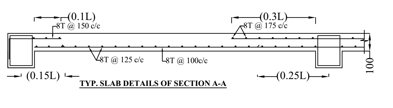
3-Slab Reinforcement:

Top Reinforcement: Here the distance from support is 0.1L from beam Corner, at the discontinuous end and in continuous slab,the distance is 0.3L.

Bottom Reinforcement: Here the distance from the center of support is 0.15L from beam Corner, or discontinuous end and in continuous slab, reinforcement distance is 0.25L from the support center. 

Reinforcement distances in both top and bottom are maintained alternatively.

4- Concealed Beam or Hidden beam: Provided within the depth of the supporting slab (i.e 125 mm). The provided reinforcement in the concealed beam was 3-12mm at top and 3-12mm at the bottom.

5- Beam Arrangement: Provided depth of beam was 450 mm and width 230mm


So this was the key point about the observations made during the site visit.


About us: Civil Center is a Civil Engineering Consultancy company which provides services ranging from Building Consultancy Services like Architectural Plan, Structural Drawing, Estimation, 3D Views of Interior and Exterior of a Building, Construction Planning and Management, and also other services like Survey Investigation Works.


We also provide industrial Training to Civil Engineering Students as well as professionals which include courses on Building Design, Detailing Estimation, 3D Modelling and Survey  by using Software like STAAD. Pro, Tekla Structural Designer, Revit Structures, Tekla Structures, MS Excel, E-Survey. In training our goal is to make our trainees ready for the industry by getting them trained in Live Projects. We also provide placement assistance to our trainees.

To join our live classes on Tekla Structural Designer and other courses related to Civil Engineering, click here : https://forms.gle/Yy9j8BH8zZzmFfZMA

For any query 

Call on: 8433248864

WhatsApp: +91 6372905201

Email: team@civilcenter.in


If you have any requirement of Building Consultancy Services like Architectural Plan, Structural Drawings etc., register using the link given below

https://forms.gle/M4MTqgcLP6ZEp4rs7

Whatsapp: +91 6372905201

Email: enquiry@civilcenter.in

Visit our Website: http://www.civilcenter.in/


Visit our Website: http://www.civilcenter.in/


You Can Find Us On Other Social Media

Visit our Facebook Page: https://www.facebook.com/civilcenter/

Visit our LinkedIn Page: https://www.linkedin.com/company/civil-center

Follow our Twitter Handle: https://twitter.com/_CivilCenter

Follow us on Instagram: https://www.instagram.com/civilcenter17/

Comments

Popular posts from this blog

STAAD Pro Vs Tekla Structural Designer .Which One Is Better ?

  Tekla Structural Designer (TSD) is a simple, integrated design & analysis software that enables engineers to deliver safe, effective and rationalized design more quickly, regardless of structural material. Reinforcement drawings for the entire building or tonnes of steel for estimating and many more.    So in the above image you can see the first image is created in Tekla Structural Designer (TSD) and in the second image the model has been created in Staad Pro  . we can start the comparison with the grid lines. So for creating grid lines in staad we need to enter the coordinates from the beam column plan as shown in fig.1 and we need to insert it while viewing the beam column plan. Fig 1 We can create grid lines in Tekla Structural Designer directly and in addition        you can also import the beam column plan as shadow as shown in fig 2 .  Fig. 2 • Next step is adding members in staad pro so in addition we need to see the beam colu...

Tekla structural Designer VS ETABS.

Tekla Structural Designer is advanced software used for Structural Analysis and Design of a Building. In Tekla, we can do the detailing of steel structures as well as RCC structures. We can create RCC buildings and we can insert the rebars in Tekla structures Designer software.  We can also do the form works and structural drawing without the help of any other software. Let’s see the difference between TSD and ETABS. Step 1 As per the modelling aspects in ETABS we can import the grid lines we cannot import the shadow of an architectural drawing and in Tekla, we can import grid lines as well as the shadow of an architectural drawing assigning beams and columns is very easy and the modelling becomes quick.  In ETABS we cannot see the extruded view easily but in TSD we can see the extruded view easily. Basically, visualization is easy in TSD as compared to ETABS.   Step 2 In TSD load application is very easy as the dead load and live load both are almost same but in the wind...

Tekla Structural Designer- How to model slant roof in TSD.

Tekla Structural Designer is advanced software used for Structural Analysis and Design of a Building. In Tekla, we can do the detailing of steel structures as well as RCC structures. We can create RCC buildings and we can insert the rebars in Tekla structures Designer software.  We can also do the form works and structural drawing without the help of any other software. Let’s go step by step to know how to model slant roofs in TSD. Step 1 First of all, we will open a new project and define some construction levels. After designing construction levels just click on ok then we will go to the base level and create some grid lines. Now we will create the gridline of 6m then make another grid line parallel to it then join these two grid lines with another two grid lines, one from the top and another from the bottom. Now extend both the parallel grid lines and insert some grid lines and we can also change the properties as per our preference.    Fig. 1 Step 2 Now we will insert...